RU 66 UT CC0 P4 B-N
Main technical Specifications
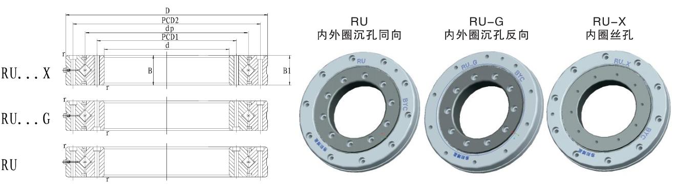
Detailed parameters and installation dimensions:
dp: 66 mm, d1: 3.1 mm, rmin: 0.6 mm, ds: 59 mm, Dh: 74 mm
NOTE: All other trademarks are the property of their respective owners, used for the purpose of compatibility description and product identification only. Tradebearings is not affiliated with, endorsed by, or sponsored by the holders of these trademarks.
RU 66 UT CC0 P4 B-N refers to a type of Crossed Roller Bearings, with dimensions 35 mm (Bore) x 95 mm (OD) x 15 mm (Width), designed for Its rollers are arranged in a 90° perpendicular cross pattern in the V-shaped raceway, primarily used in industrial robot joints, CT scanner gantry, for applications Within a compact space, it simultaneously withstands high-precision radial loads, axial loads, and tilting moments. it's built to handle significant loads (dynamic radial: 17500 N, static radial: 22300 N, ), It weight approximately 0.62 kilogram.
- Min. Order: 1 Piece/(RU 66 UT CC0 P4 B-N, 35 = ID, 95 = OD, 15 = B, 0.62 kg) or according to different suppliers
- Price: Different brands, different quality, different RU 66 UT CC0 P4 B-N prices, different suppliers and different quality determine different prices, you can ask the supplier in detail for the price according to your own needs.
- Precision Rating: DIN: P2~P0; ANSI: ABEC9~ABEC1; JIS: JIS~JIS0; ISO: CLASS2~NORMAL CLASS; GB/T30794 B~G
- Inquiry ways: The right of the inquiry form, Email, skype, Whatsapp


✨What are the Benefits of choosing RU 66 UT CC0 P4 B-N bearings?
🏭 What are the applications of the RU 66 UT CC0 P4 B-N bearing?
📐 How should choose the right model for a Crossed Roller Bearings?
Selection of Crossed Roller Bearings
The core of selection is ensuring that the bearing's precision, rigidity, and load-bearing capacity meet the specific operating requirements of the equipment.
1. Structural Form: Selection is based on the installation requirements of the rotating parts: For outer ring rotation, use a split inner ring type; for inner ring rotation, use a split outer ring type; for both inner and outer rings rotating with high precision, use an integral structure (such as RU, CRBH type).
2. Size Range: The primary basis is the installation space of the equipment, determining the required inner diameter, outer diameter, and width.
3. Precision and Clearance: These are the core determinants of performance. Negative clearance improves rigidity and lifespan but increases friction; positive clearance is beneficial for high-speed operation but may reduce rigidity. A comprehensive selection must be made considering both speed and rigidity requirements.
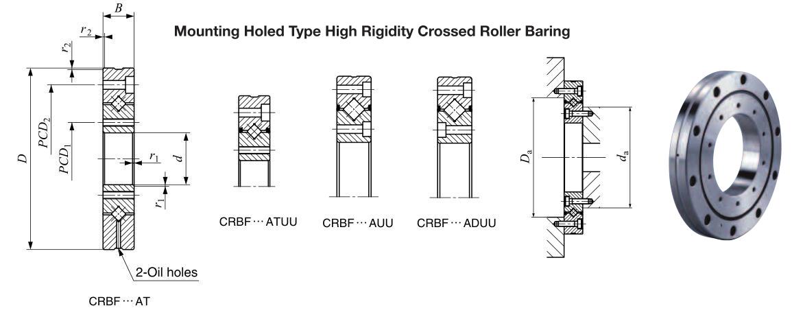
4. Installation Method: Mainly divided into two categories: 1) Bearings with mounting holes on both inner and outer rings can be directly fixed with bolts; 2) Bearings without mounting holes require fixing via clamping flanges and bearing housings.
5. Load Capacity: Based on the radial force, axial force, and tilting moment that the equipment will bear, refer to the rated load table in the bearing catalog to select a model with sufficient load capacity and a certain margin.
6. Operating Environment: Consider the operating temperature, humidity, and cleanliness to select appropriate internal clearance, grease, and sealing type.
🛠️ What is the mounting procedure for RU 66 UT CC0 P4 B-N bearings?
Key Points for Installing Crossed Roller Bearings
Due to their thin-walled structure, improper installation can easily cause deformation. The following procedure must be strictly followed.
Preparation Before Installation
Environmental Inspection: Conduct the inspection in a dry, clean environment.
Component Cleaning: Clean the bearing housing and mounting surfaces to remove dirt and burrs.
Structural Rigidity Confirmation: The rigidity of the mounting section is crucial; insufficient rigidity will significantly reduce bearing performance.
Installation Process
Gently Press In: Apply even pressure to the end face of the raceway and gently tap it circumferentially with a plastic hammer. Slowly and horizontally install the bearing; direct tapping is strictly prohibited.
Flange Installation: After placing the flange, slightly wiggle it to adjust the bolt position. Tighten the bolts by hand to confirm accurate thread alignment.
Bolt Tightening: Tighten in 3 to 4 stages, repeatedly tightening diagonally to the specified torque. During tightening, the integral raceway can be slightly rotated to correct the joint of the split races.
Post-installation inspection
Rotation test: After manually confirming smooth rotation, conduct a no-load, low-speed test run, gradually increasing the speed and load while monitoring noise, vibration, and temperature rise. Stop immediately if any abnormality is detected.
📋 Special Note for mounting RU 66 UT CC0 P4 B-N bearings?
Special Notes
Seam Treatment of Split Rings: Before installation, if any misalignment is found in the seam of the inner or outer ring, loosen the fixing bolts, gently tap it with a plastic hammer to correct the misalignment, and then install. Do not force assembly.
Precautions for Fixing Bolts: During installation or disassembly, never apply additional external force (such as hammering) to the connecting bolts to avoid damaging the threads or bolts.
Grease Management: The bearings come with grease at the factory and can be used directly. Afterward, high-quality grease should be added every 3 to 6 months. Initially, resistance will be higher after adding grease; after operation, excess grease will overflow, and the torque will return to normal.
Operating Temperature Limits: The standard operating temperature range for crossed roller bearings is -20 to 120°C. However, for types with spacers or seals, the maximum allowable temperature and continuous operating temperature will be lower, requiring special attention.
Positioning Holes and Plugs: For bearings with mounting holes, the roller insertion holes usually have plugs. During installation, ensure that the plugs are positioned away from the area of maximum load to prevent stress concentration.
If you can provide more specific application scenarios (such as robot joints, machine tool turntables) or load parameters, I can do a more in-depth selection analysis for you.
💬 User feedback on Crossed Roller Bearings:
I. Positive Feedback: It Truly Solves Pain Points
"Excellent rigidity, improved surface finish on the rotary table."
Typical Scenarios: CNC rotary tables, direct drive motor (DDR) applications.
User's words: "Previously, using a combination of thrust ball bearings and deep groove ball bearings, there was always a slight elasticity that caused tool marks. After switching to crossed roller bearings, the tool marks have significantly improved because the rollers are arranged in a cross pattern, resulting in minimal deformation when subjected to overturning moments."
"Installation space is reduced by half, and the structure is simplified."
Typical Scenarios: Robot joints (harmonic reducer output end), thin rotary tables.
User's words: "A single bearing can simultaneously withstand radial, axial, and moment loads, eliminating the need for complex bearing housing combinations, allowing the equipment to be made very thin."
"Very smooth operation, no crawling at low speeds."
Typical Scenarios: Optical scanning equipment, precision alignment stages.
Reason: Due to the typically negative clearance (preload) design, the rolling elements do not slip, resulting in uniform friction and thus exhibiting excellent smoothness at micro-motions or low speeds.
II. Negative Feedback: Pain Points and Complaints
Feedback 1: "Jagged" or "Unsmooth Rotation" After Installation
User Description: "It felt great when first installed, but after tightening the bolts, it jerks and sometimes doesn't rotate at all."
Cause Analysis:
Incorrect Mounting Surface Flatness (Most Common): The raceway walls of crossed roller bearings are very thin (especially in split inner or outer ring designs). While their rigidity is sufficient relative to the raceway itself, they are extremely prone to deformation due to changes in the mounting surface. If the flatness of the mounting base does not meet the requirements (usually a few micrometers to tens of micrometers), the raceway will twist when the bolts are tightened.
Incorrect Mounting Screw Tightening Sequence: Failure to use diagonal cross-tightening leads to stress concentration.
Foreign Object Ingress: Iron filings or burrs may have entered during installation, damaging the rollers.
Feedback 2: "Decreased Precision" or "Gap Appears" After a Period of Use
User Description: "After six months of use, the turntable started to wobble, and the backlash increased."
Cause Analysis:
Loss of Preload: Crossed roller bearings typically rely on negative clearance (preload) to maintain rigidity. If the initial preload is insufficient, or if permanent plastic deformation (indentation) occurs in the raceway due to impact loads, the original negative clearance will become positive clearance, leading to a decrease in rigidity.
Raceway Wear: Poor lubrication is the main cause. The roller end faces and flanges of crossed roller bearings experience sliding friction. If the grease fails to reach the contact area, abnormal wear will occur.
Feedback 3: Loud Operating Noise and Abnormal Sounds
User Description: "It makes a 'humming' sound when rotating, or an intermittent 'clunking' sound."
Cause Analysis:
'Clunking' Sound: This is usually caused by the rollers passing through the ball-filling holes (ball-filling notches) during installation. If the bearing design includes a ball loading notch, and this notch is located in the heavy-load area during installation, slight vibration and noise will occur each time the roller passes over it.
A "humming" sound: This may be caused by a roller getting stuck or cage friction.
Feedback 4: Cage breakage or disintegration
User description: "Upon disassembly, the nylon cage inside was broken."
Cause analysis:
High-speed applications: Crossed roller bearings are suitable for medium to low-speed rotation. If used for continuous high-speed rotation (e.g., exceeding several hundred rpm), the centrifugal force of the rollers will exert enormous pressure on the cage.
Stuck due to poor lubrication: After the rollers get stuck, the cage is forced to withstand abnormal forces and break.
Impact load: Sudden impacts cause the rollers to shift instantaneously, cracking the cage.
III. "Troubleshooting Guide" Implicit in User Feedback
Based on the experience and lessons learned from numerous users, the following valuable suggestions are summarized:
1. Regarding the mounting surface (a lesson learned the hard way)
Do not place directly on a rough surface: The mounting base must be finely ground or scraped. Many users have reported that newly purchased high-precision bearings immediately lose their precision when installed on an untreated welded base.
1. Thin-walled structures require thick flanges: If the flange wall is too thin, it will deform after tightening. It is recommended that the flange thickness be sufficient or that reinforcing ribs be designed.
2. Regarding the location of the ball-loading hole (notch):
If the bearing has a ball-loading notch (plug), ensure that the plug is positioned away from the main load-bearing area during installation. It is generally recommended to place the plug in the area of least stress (e.g., on a horizontally mounted turntable, place it on the side or back).
3. Regarding the selection of grease:
Do not use grease that is too thick: Because the rollers and raceways have line contact, the grease needs good extreme pressure and penetrating properties. If the grease is too thick, it will not reach the contact area between the rollers and the flanges, accelerating wear.
Factory grease is not a one-time fix: Many users believe that once the grease is applied at the factory, it doesn't need further attention. Crossed roller bearings typically require periodic (e.g., every 3-6 months) grease replenishment through the lubrication hole to remove old, ineffective grease.
4. Regarding the installation of split-type bearings (inner and outer rings separable):
For crossed roller bearings with separate inner or outer rings, do not arbitrarily disassemble the two half-rings during installation unless you intend to readjust the preload. If disassembled, ensure the two half-rings are aligned during reinstallation (usually indicated by locating pins or markings); otherwise, raceway misalignment will cause the bearing to seize.
In summary, over 90% of user dissatisfaction with crossed roller bearings stems from improper installation foundation treatment. As long as the mounting surface accuracy is up to standard, the tightening process is correct, and lubrication is adequate, it is indeed the best choice for achieving a high-rigidity, compact rotation solution.
Are you experiencing a specific fault? If so, please describe the type of equipment and the operating environment; this may help you determine the cause more accurately.